Start Here
What Is Verilog HDL?
Verilog is a hardware description language: text that models digital circuits for simulation and describes synthesizable hardware for implementation.
4 min read · Updated
Verilog is a hardware description language (HDL) used to model digital circuits. Synthesizable Verilog describes structures such as combinational logic, registers, and connections; simulation-only Verilog supplies stimulus, timing, checks, and diagnostic output around that design.
Verilog became an IEEE standard as IEEE 1364. The important beginner distinction is not “hardware instead of execution.” A simulator really does execute the language’s processes. The distinction is that those processes model concurrent hardware behavior, and only a synthesizable subset can be translated into an implementation.
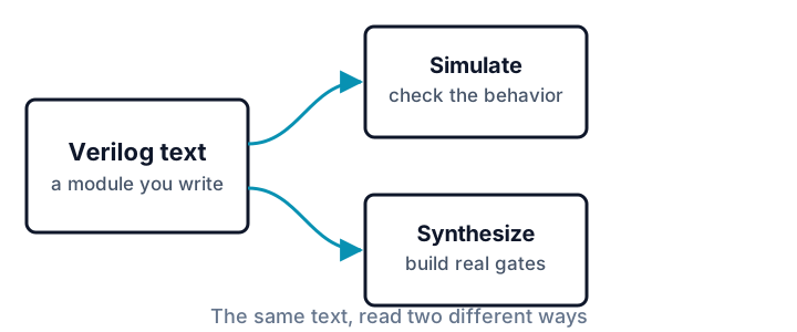
- A simulator executes the Verilog model. A testbench supplies inputs and checks whether observed behavior matches the specification.
- A synthesis tool translates synthesizable design code into an optimized netlist, often mapped to a target technology as part of the synthesis flow. Later implementation tools turn that netlist into an FPGA configuration or a physical-chip design.
Simulation success alone does not prove that code is synthesizable or that the resulting hardware matches the designer’s intent. Tests, assertions, lint, synthesis reports, and technical review each answer different questions.
Concurrency between processes, sequence inside a process
Independent initial and always processes, continuous assignments, and instantiated modules operate concurrently. Their behavior is triggered by time or signal events rather than serialized by their position in the file.
Inside one procedural block, however, statements execute in procedural order. That local ordering is why blocking and non-blocking assignments can produce different results later in the course. A safe mental model is:
- between processes: concurrent;
- inside one procedural process: ordered statements plus event-scheduling rules;
- in physical hardware: components operate concurrently with real propagation and timing constraints.
Zero-delay RTL simulation abstracts physical propagation delay. It may use internal zero-time scheduling steps, often called delta cycles, to settle dependent logic without advancing $time.
Predict before running
The testbench below declares process A, then B, then C. Each wakes at a different simulated time. Process A also proves that its own statements remain ordered: it changes switch, deliberately waits one testbench time unit for a clean observation point, and then reads lit.
Before running it, predict the print order. Will declaration order force A, B, C, or will the delays determine which process prints next?
`timescale 1ns/1ps

module bulb (
  input  wire switch,
  output wire lit
);
  assign lit = switch;
endmodule

module tb;
  reg switch;
  wire lit;
  bulb u_bulb(.switch(switch), .lit(lit));

  // Testbench process A: statements inside this block remain ordered.
  initial begin
    switch = 1'b0;
    #1;
    $display("t=%0t block A: switch=%b lit=%b", $time, switch, lit);
    if (lit !== 1'b0) begin $display("FAIL A0"); $finish; end

    #9 switch = 1'b1;
    #1;
    $display("t=%0t block A again: switch=%b lit=%b", $time, switch, lit);
    if (lit !== 1'b1) begin $display("FAIL A1"); $finish; end
    $display("PASS");
  end

  // Testbench processes B and C run concurrently with A.
  initial begin
    #6 $display("t=%0t block B", $time);
  end

  initial begin
    #3 $display("t=%0t block C", $time);
    #9 $finish;
  end
endmodule
Expected output:
t=1000 block A: switch=0 lit=0
t=3000 block C
t=6000 block B
t=11000 block A again: switch=1 lit=1
PASS
Icarus prints time in the testbench precision unit here, so 1 ns appears as 1000 ps. Process C is declared last but prints before B. Process A’s two reads still occur in the order written inside A.
The #1 delays, $display, checks, and $finish belong to the testbench. They make the simulation deterministic and observable; they do not describe delays or print hardware in the synthesized bulb. The synthesizable design is the bulb module and its continuous connection.
What Verilog is not
- Not only a hardware netlist language. Simulation-oriented Verilog also includes delays, file I/O system tasks such as
$fopen/$fdisplay, diagnostic tasks, and testbench control flow. - Not globally top-to-bottom. File order does not serialize independent processes, although statement order inside an individual procedural block still matters.
- Not automatically synthesizable because it simulates. Arbitrary delays, testbench file I/O,
$display,$finish, and many other verification constructs have no direct hardware implementation. - Not automatically correct because it synthesizes. Synthesis translates the behavior it recognizes; it does not know the unstated intent of the design.
Where to go from here
Where Verilog Fits in the Toolchain places it among simulators, linters, synthesis, and implementation tools. What Is RTL? then narrows the focus to register-transfer-level design.
Sources and verification
Example provenance: SkillLift Labs authored the example for this tutorial. tests/scripts/tutorial-verified-examples.test.ts extracts the complete marked example from this Markdown file, compiles it in Verilog-2005 mode with Icarus Verilog, runs it, and requires the simulator output to match the Expected output block. The same test also carries an independent, code-owned semantic oracle for the process order and values, and exercises the article-to-runner source-splitting path. Automation verifies those stated properties; human technical review for indexing remains a separate gate.