Sequential RTL
Linear Feedback Shift Register (LFSR) in Verilog
Build and verify a four-bit linear feedback shift register, trace its 15 nonzero states, understand the zero lock-up, and separate deterministic simulation from hardware randomness claims.
4 min read · Updated
A linear feedback shift register (LFSR) is a shift register whose next input bit is an XOR of selected state bits. The sequence is deterministic: the same nonzero seed produces the same repeating states every time. A carefully chosen feedback rule can visit every nonzero state before repeating; for four bits, that maximum period is 2^4 - 1 = 15 states.
Prerequisites: clocked registers, non-blocking assignments, concatenation, XOR, binary counting, and tracing one state per rising edge. Review Shift Registers first.
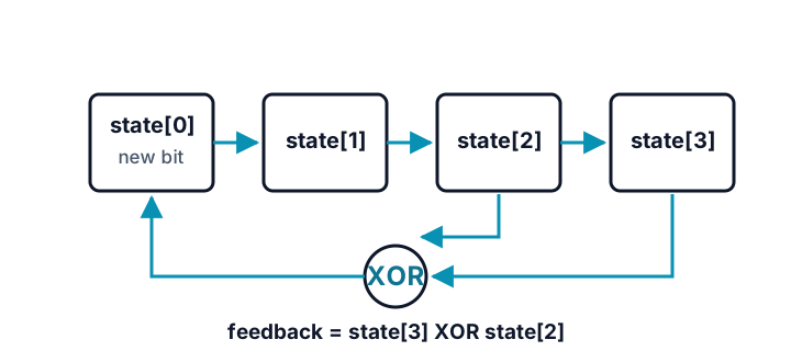
This page uses the explicit update state <= {state[2:0], state[3] ^ state[2]} and the seed 4'b0001. The testbench does not trust a few example values: it records every visited state, rejects zero, rejects an early repeat, and requires a return to the seed after exactly 15 updates.
Predict before running
Starting from 0001, write the next two states before running. Then write one sentence explaining why the all-zero seed can never escape. Use the exact rule above rather than guessing from the eventual output pattern.
`timescale 1ns/1ps

module lfsr4 (
  input wire clk,
  input wire rst,
  output reg [3:0] state
);
  wire feedback = state[3] ^ state[2];

  always @(posedge clk) begin
    if (rst) state <= 4'b0001;
    else state <= {state[2:0], feedback};
  end
endmodule

module tb;
  reg clk, rst;
  wire [3:0] state;
  reg [15:0] seen;
  integer step;

  lfsr4 dut (.clk(clk), .rst(rst), .state(state));
  always #5 clk = ~clk;

  initial begin
    clk = 1'b0;
    rst = 1'b1;
    seen = 16'h0000;

    repeat (2) @(posedge clk);
    @(negedge clk);
    rst = 1'b0;

    for (step = 1; step <= 15; step = step + 1) begin
      @(posedge clk); #1;
      if (state === 4'b0000) begin $display("FAIL ZERO STATE"); $finish; end
      if (seen[state]) begin $display("FAIL EARLY REPEAT state=%04b", state); $finish; end
      seen[state] = 1'b1;
      $display("STEP %0d state=%04b", step, state);
    end

    if (state !== 4'b0001 || seen !== 16'hFFFE) begin
      $display("FAIL PERIOD state=%04b seen=%04h", state, seen);
      $finish;
    end

    $display("UNIQUE_STATES=15 RETURN=0001");
    $display("PASS");
    $finish;
  end
endmodule
Expected output — reveal after you predict
STEP 1 state=0010
STEP 2 state=0100
STEP 3 state=1001
STEP 4 state=0011
STEP 5 state=0110
STEP 6 state=1101
STEP 7 state=1010
STEP 8 state=0101
STEP 9 state=1011
STEP 10 state=0111
STEP 11 state=1111
STEP 12 state=1110
STEP 13 state=1100
STEP 14 state=1000
STEP 15 state=0001
UNIQUE_STATES=15 RETURN=0001
PASS
The third state is 1001: shifting 0100 left keeps 100, and state[3] ^ state[2] is 0 ^ 1 = 1. Zero is different. If every state bit is zero, the XOR feedback is also zero, so the next state is zero forever. A usable LFSR must therefore load or reset to a nonzero seed.
Hardware it describes
The generic structure is four flip-flops, a two-input XOR feeding the new bit, and wires connecting the shift path. The automated Yosys prep check requires sequential storage and XOR logic in its coarse netlist, and a separate generic synth pass must finish. A target tool may fold or place those resources differently, but no memory, software random-number generator, or hidden state is implied by this source.
Simulation, synthesis, and implementation are different claims
- Simulation: proves this exact seed and feedback rule traverse 15 distinct nonzero states and then repeat.
- Generic synthesis: conservative
prepproves the source is accepted as coarse sequential hardware with XOR feedback; the separate completesynthscript proves generic synthesis finishes. Neither proves placement, maximum frequency, or statistical quality. - Implementation: clock quality, reset delivery, physical timing, and any use as a test-pattern source belong to the target flow. Those are not modeled by this testbench.
Limitations
- An LFSR is not cryptographically secure and is not a source of entropy. Its future states are predictable from its current state.
- A tap rule that works for one width cannot be copied blindly to another. This article verifies only the four-bit rule shown.
- The output sequence depends on shift direction, bit numbering, tap convention, and seed. Different correct conventions can print different sequences.
- The example has no enable, reseed port, parallel output qualification, or protocol wrapper.
Sources and verification
Example provenance: SkillLift Labs authored this design, exhaustive 15-state self-check, diagram, and explanation. tests/scripts/tutorial-verified-examples.test.ts compiles and runs the complete marked example with Icarus Verilog, requires exact published output, and compares it with an executable recurrence model; a deliberate wrong-tap mutation must disagree with that model. tests/scripts/tutorial-tut8-synthesis.test.ts runs warning-enabled compilation, requires sequential storage and XOR logic after Yosys prep, and separately requires complete generic synth. Automation does not claim randomness, cryptographic strength, human review, or device timing.