Finite State Machines
Two-Process FSM Pattern in Verilog
Build a Verilog finite-state machine with one clocked state register and one combinational next-state process, including complete assignments and an explicit invalid-state policy.
3 min read · Updated
A two-process finite-state machine separates storage from decision logic. One edge-triggered always block stores the current state; one intended-combinational always @(*) block calculates the next state.
It is a coding pattern, not a Verilog requirement. A well-written one-process or three-process FSM can also be correct. Whatever pattern you use, keep its reset, assignment, and state-transition semantics explicit.
Architecture at a glance
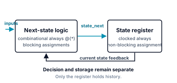
| Process | Event control | Assignment style | Job |
|---|---|---|---|
| State register | posedge clk |
non-blocking <= |
apply reset and store state_next |
| Next-state logic | * |
blocking = |
calculate state_next from current state and inputs |
This state register has an active-low synchronous reset. Because rst_n is absent from the event control, asserting it changes the state only at a rising clock edge:
always @(posedge clk) begin
  if (!rst_n) state <= IDLE;
  else        state <= state_next;
end
The combinational process assigns a hold value before considering overrides:
always @(*) begin
  state_next = state;
  case (state)
    IDLE:     if (start) state_next = REQUEST;
    REQUEST:            state_next = WAIT_ACK;
    WAIT_ACK: if (ack)  state_next = COMPLETE;
    COMPLETE: if (!start) state_next = IDLE;
    default:             state_next = IDLE;
  endcase
end
The default-at-top covers input conditions that do not request a transition. The default: case item defines RTL behavior for bit patterns not listed as named states.
That case item is useful defensive RTL, but it is not by itself a guarantee of physical fault recovery. Synthesis may recode or optimize an FSM. If recovery from hardware upsets is a requirement, use the target tool’s safe-state controls, inspect the synthesized encoding, and verify the implemented recovery behavior.
Transition table
| Current state | Transition condition | Next state when true | Otherwise |
|---|---|---|---|
IDLE |
start=1 |
REQUEST |
hold IDLE |
REQUEST |
unconditional | WAIT_ACK |
— |
WAIT_ACK |
ack=1 |
COMPLETE |
hold WAIT_ACK |
COMPLETE |
start=0 |
IDLE |
hold COMPLETE |
| unlisted encoding | any | IDLE in RTL |
— |
Predict, compile, and run
This four-state request/acknowledge controller deliberately differs in state count, inputs, and transition structure from the course’s graded FSM builds.
After reset is released, start is asserted. Predict the first two states. Then ack is asserted, followed by start being cleared.
`timescale 1ns/1ps

module request_controller(
  input wire clk,
  input wire rst_n,
  input wire start,
  input wire ack,
  output reg [2:0] state
);
  localparam [2:0] IDLE = 3'd0, REQUEST = 3'd1,
                   WAIT_ACK = 3'd2, COMPLETE = 3'd3;
  reg [2:0] state_next;

  always @(posedge clk) begin
    if (!rst_n) state <= IDLE;
    else        state <= state_next;
  end

  always @(*) begin
    state_next = state;
    case (state)
      IDLE:     if (start)  state_next = REQUEST;
      REQUEST:              state_next = WAIT_ACK;
      WAIT_ACK: if (ack)    state_next = COMPLETE;
      COMPLETE: if (!start) state_next = IDLE;
      default:              state_next = IDLE;
    endcase
  end
endmodule

module tb;
  reg clk, rst_n, start, ack;
  wire [2:0] state;

  request_controller dut(clk, rst_n, start, ack, state);
  always #5 clk = ~clk;

  task check;
    input [2:0] expected;
    input integer cycle;
    begin
      $display("CYCLE %0d state=%0d", cycle, state);
      if (state !== expected) begin $display("FAIL CYCLE %0d", cycle); $finish; end
    end
  endtask

  initial begin
    clk = 1'b0; rst_n = 1'b0; start = 1'b0; ack = 1'b0;
    @(posedge clk); #1;
    if (state !== 3'd0) begin $display("FAIL RESET"); $finish; end

    @(negedge clk); rst_n = 1'b1; start = 1'b1;
    @(posedge clk); #1; check(3'd1, 1);
    @(posedge clk); #1; check(3'd2, 2);

    @(negedge clk); ack = 1'b1;
    @(posedge clk); #1; check(3'd3, 3);

    @(negedge clk); start = 1'b0; ack = 1'b0;
    @(posedge clk); #1; check(3'd0, 4);

    $display("PASS");
    $finish;
  end
endmodule
Expected output:
CYCLE 1 state=1
CYCLE 2 state=2
CYCLE 3 state=3
CYCLE 4 state=0
PASS
The testbench changes inputs on falling edges, away from the rising sampling edge, and observes state one time unit after each rising edge. That avoids a testbench/design race and gives scheduled non-blocking updates time to settle.
Review checklist
- Is exactly one process responsible for writing the state register?
- Does the state register use non-blocking assignment?
- Is the reset polarity and synchronous/asynchronous behavior stated correctly?
- Does the combinational process assign every procedural result on every path?
- Does every named state have intentional behavior for every input condition?
- Is the invalid-state policy described as RTL behavior rather than guaranteed physical fault tolerance?
Sources and verification
- lowRISC Verilog Coding Style Guide: finite-state machines
- AMD Vivado Synthesis: FSM safe-state handling
Example provenance: SkillLift Labs authored this four-state handshake as a parallel example, not as a course FSM answer. tests/scripts/tutorial-verified-examples.test.ts compiles it in Verilog-2005 mode, reproduces the published output, and independently checks synchronous reset and all four transitions. Automation verifies those stated properties; human technical review for indexing remains a separate gate.