Hierarchy and Datapaths
Datapath vs Control: The Split That Makes RTL Systems Readable
A practical guide to separating stored and transformed values from the control decisions that route them through an RTL system.
4 min read · Updated
A digital system becomes easier to understand when you separate two responsibilities:
- The datapath stores, moves, and transforms values.
- The controller decides which datapath action happens now.
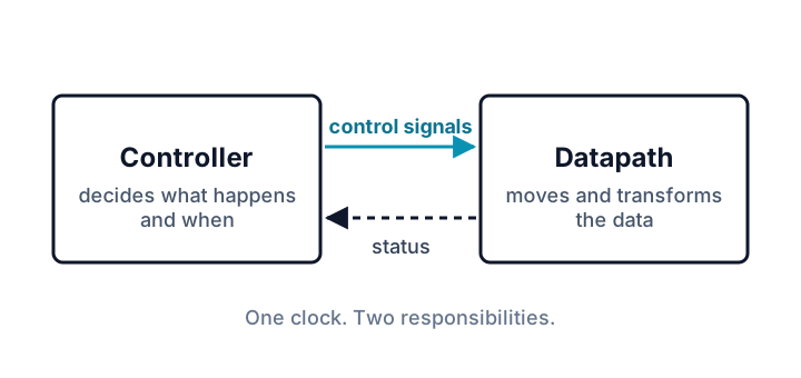
This is not merely a drawing convention. It gives you a repeatable way to read a larger RTL design, choose useful signal names, and locate whether a wrong result came from the value route or from the decision that selected it.
What belongs in the datapath?
Datapath signals answer questions such as “what value is stored?”, “which value is moving?”, and “what transformation is applied?”
Typical datapath blocks include:
- registers and memories, which store values;
- buses, which carry related bits together;
- MUXes, which select one data source;
- adders, shifters, comparators, and ALUs, which transform values.
A route might read:
sensor input -> source MUX -> offset adder -> adjusted sampleWidths belong to that route. An eight-bit source connected to an eight-bit destination behaves differently from a deliberate extension or truncation.
What belongs in control?
Control signals answer questions such as “which source should the MUX choose?”, “which operation should execute?”, and “should a destination register load on this edge?”
Typical examples include:
- a source-select bit;
- an operation code;
- a write enable;
- state values inside an FSM controller.
Control signals are often one bit or a few bits wide because they choose actions. They are not the payload being stored or transformed.
Read an operation in two passes
Imagine a monitor that chooses one of two eight-bit sensor samples and adds a calibration offset.
Read the datapath first:
- Two sensors provide candidate values.
- A MUX routes one sample forward.
- An adder applies the offset.
- The adjusted value continues to the next block.
Then read the control:
choose_fastselects the sensor source.- Any later load-enable signal would decide whether a register captures the adjusted value.
The route and the decisions operate together, but they answer different questions.
Predict before running
This deliberately uses a sensor/calibration path rather than the course’s register-file/ALU build. slow_sample=12, fast_sample=40, and calibration=3.
Before running it, predict the adjusted value for each setting of choose_fast.
module add_calibration (
  input  wire [7:0] sample,
  input  wire [7:0] calibration,
  output wire [7:0] adjusted
);
  assign adjusted = sample + calibration;
endmodule

module sensor_path (
  input  wire [7:0] slow_sample,
  input  wire [7:0] fast_sample,
  input  wire [7:0] calibration,
  input  wire       choose_fast,
  output wire [7:0] adjusted_sample
);
  wire [7:0] selected_sample;

  assign selected_sample = choose_fast ? fast_sample : slow_sample;
  add_calibration u_adjust(
    .sample(selected_sample),
    .calibration(calibration),
    .adjusted(adjusted_sample)
  );
endmodule

module tb;
  reg [7:0] slow_sample, fast_sample, calibration;
  reg choose_fast;
  wire [7:0] adjusted_sample;

  sensor_path dut(
    .slow_sample(slow_sample),
    .fast_sample(fast_sample),
    .calibration(calibration),
    .choose_fast(choose_fast),
    .adjusted_sample(adjusted_sample)
  );

  initial begin
    slow_sample = 8'd12;
    fast_sample = 8'd40;
    calibration = 8'd3;

    choose_fast = 1'b0; #1;
    $display("choose_fast=%0d source=slow adjusted=%0d", choose_fast, adjusted_sample);
    if (adjusted_sample !== 8'd15) begin $display("FAIL SLOW"); $finish; end

    choose_fast = 1'b1; #1;
    $display("choose_fast=%0d source=fast adjusted=%0d", choose_fast, adjusted_sample);
    if (adjusted_sample !== 8'd43) begin $display("FAIL FAST"); $finish; end

    $display("PASS");
    $finish;
  end
endmodule
Expected output:
choose_fast=0 source=slow adjusted=15
choose_fast=1 source=fast adjusted=43
PASSslow_sample, fast_sample, selected_sample, calibration, and adjusted_sample are datapath values. choose_fast is the control decision. Changing the control bit changes which value travels through the MUX; the calibration block itself does not change.
This example is combinational: it contains no clock and no storage. Adding a destination register would introduce a separate sequential decision—typically a clock edge plus a load enable.
Why the split helps with debugging
When a result is wrong, use the same two-pass method:
- Follow the data. Did the expected source value reach the selected input? Were widths preserved? Did the transform receive the intended operands?
- Check the decisions. Did the MUX select the intended source? Was the operation code correct? Was a load enable active on the intended edge?
A correct value sitting on an unselected MUX input suggests a control problem. A correctly selected but truncated value suggests a datapath-width problem.
A useful review habit
For every operation, complete one sentence for each side:
- Datapath: “This value moves from _ through _ into ___.”
- Control: “These signals choose that route and permit the destination action.”
If either sentence is hard to complete, the top-level wiring or signal names may need to become clearer.
Sources and verification
Example provenance: SkillLift Labs authored this sensor-path example as a parallel circuit, not as a course datapath answer. tests/scripts/tutorial-verified-examples.test.ts compiles it in Verilog-2005 mode, reproduces the published output, and independently checks both control selections. Automation verifies those stated properties; human technical review for indexing remains a separate gate.