Designs and Projects
16-Step PWM Generator in Verilog
Build a vendor-neutral 16-step PWM generator with a 4-bit phase counter, verify 0%, 50%, 100%, and out-of-range saturation, and understand its frequency and update limitations.
5 min read · Updated
Pulse-width modulation (PWM) represents a level by changing the fraction of each repeating period that a one-bit output stays high. In a digital RTL generator, a free-running counter supplies the phase and a comparator drives the output high while phase < duty.
Prerequisites: 4-bit counters and wraparound, unsigned comparison, continuous assignment, synchronous reset, and sampling signals after clock edges. This is a logic-only design: no FPGA board, pin constraint, motor, LED, power stage, or vendor IP is required or implied.
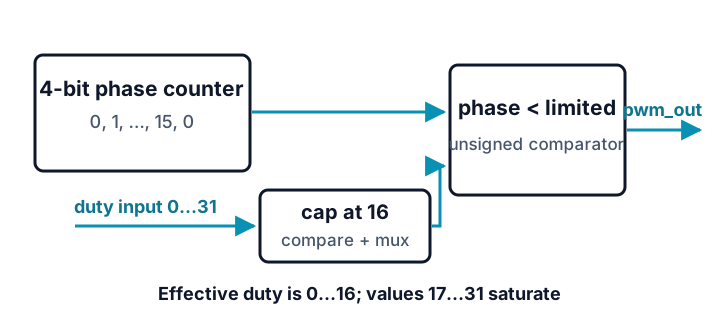
The example uses a 4-bit phase counter, so one PWM period contains 16 clock ticks. Its 5-bit duty port can physically represent 0 through 31. Values 0 through 16 request that many high ticks; values 17 through 31 are explicitly saturated to 16 so every possible input has defined behavior:
duty |
High ticks per 16-tick period | Duty fraction |
|---|---|---|
| 0 | 0 | 0% |
| 8 | 8 | 50% |
| 16 | 16 | 100% |
| 17–31 | 16 (saturated) | 100% |
Using a 5-bit setting is deliberate. A 4-bit value can represent only 0 through 15, so it cannot name the all-high 16/16 case without a separate special rule.
Predict before running
Before running, predict the high-tick counts for duty = 5, duty = 16, and duty = 31. For duty = 5, also list the phase values that make pwm_out high.
Then try this separate thought experiment: if the input clock were 16 MHz, what would the PWM repetition frequency be? The testbench below actually uses a 10 ns clock period (100 MHz) only to run the digital simulation; it does not simulate a 16 MHz clock or a physical output pin.
`timescale 1ns/1ps

module pwm16 (
  input  wire       clk,
  input  wire       rst,
  input  wire [4:0] duty,
  output wire       pwm_out
);
  reg [3:0] phase;
  wire [4:0] duty_limited = (duty > 5'd16) ? 5'd16 : duty;

  always @(posedge clk) begin
    if (rst) phase <= 4'd0;
    else phase <= phase + 4'd1;
  end

  assign pwm_out = {1'b0, phase} < duty_limited;
endmodule

module tb;
  reg clk, rst;
  reg [4:0] duty;
  wire pwm_out;
  integer tick;
  integer high_ticks;

  pwm16 dut (.clk(clk), .rst(rst), .duty(duty), .pwm_out(pwm_out));
  always #5 clk = ~clk;

  task measure_period;
    input [4:0] requested_duty;
    integer effective_duty;
    begin
      effective_duty = (requested_duty > 16) ? 16 : requested_duty;
      @(negedge clk);
      duty = requested_duty;
      while (dut.phase !== 4'd15) @(negedge clk);

      high_ticks = 0;
      for (tick = 0; tick < 16; tick = tick + 1) begin
        @(posedge clk); #1;
        if (pwm_out === 1'b1) high_ticks = high_ticks + 1;
        else if (pwm_out !== 1'b0) begin $display("FAIL UNKNOWN OUTPUT"); $finish; end
      end

      $display("requested=%0d effective=%0d high_ticks=%0d",
               requested_duty, effective_duty, high_ticks);
      if (high_ticks !== effective_duty) begin $display("FAIL DUTY"); $finish; end
    end
  endtask

  initial begin
    clk = 1'b0;
    rst = 1'b1;
    duty = 5'd0;
    repeat (2) @(posedge clk);
    @(negedge clk);
    rst = 1'b0;

    measure_period(5'd0);
    measure_period(5'd8);
    measure_period(5'd16);
    measure_period(5'd31);

    $display("PASS");
    $finish;
  end
endmodule
Expected output — reveal after you predict
requested=0 effective=0 high_ticks=0
requested=8 effective=8 high_ticks=8
requested=16 effective=16 high_ticks=16
requested=31 effective=16 high_ticks=16
PASS
For duty = 5, phases 0 through 4 are high and phases 5 through 15 are low. duty = 16 and the saturated duty = 31 are both high for all 16 ticks. In the thought experiment, the output period is 16 input-clock ticks, so a 16 MHz clock would produce a 1 MHz PWM repetition rate. That arithmetic is a ratio, not a simulated clock result or a claim about a particular device or usable load frequency.
Hardware it describes
Conservative Yosys prep retains a 4-bit state register, increment logic, a greater-than comparison and mux for the saturating clamp, and an unsigned less-than comparison for the PWM output. A separate generic synth pass must also finish. The output is combinational: after phase or duty_limited changes, pwm_out follows the new comparison. A target tool chooses the physical flip-flops, carry resources, LUTs, gates, routing, and output buffer.
Simulation, synthesis, and implementation are different claims
- Simulation: counts high samples over complete 16-tick periods at 0%, 50%, and 100%, checks that an out-of-range value saturates to 100%, and fails on an unknown output or wrong count.
- Generic synthesis: conservative
prepconfirms sequential state, increment, clamp, and comparison operations in a coarse Yosys netlist; the separate completesynthscript proves generic synthesis finishes. Neither pass selects a device. - Implementation: output edge quality, pin voltage, drive strength, dead time, load behavior, electromagnetic effects, and safe power switching are outside this RTL example. Never drive a motor or power transistor directly from a logic pin merely because simulation passed.
Limitations
dutyis assumed synchronous and stable enough for the consuming clock domain. An asynchronous control needs a deliberate crossing scheme.- A duty change takes effect on the next comparison, which can make the current period contain a mixed old/new setting. Production PWM blocks often latch a new duty value at the period boundary.
- Saturation makes every 5-bit input deterministic, but it can hide a software/configuration error. A production interface may also expose an invalid-setting flag.
- There is no programmable prescaler, complementary output, dead-time insertion, center-aligned mode, or fault shutdown.
- Increasing resolution increases the period length: an
N-bit phase counter repeats every2^Nclock ticks.
Sources and verification
Example provenance: SkillLift Labs authored the RTL, self-checking measurement task, diagram, and timing explanation. tests/scripts/tutorial-verified-examples.test.ts compiles and runs the complete example with Icarus Verilog and requires exact agreement with both the published four-period result and an executable 16-phase reference model, including duty = 31 saturation. tests/scripts/tutorial-tut8-synthesis.test.ts enables compiler warnings, inspects the coarse Yosys prep netlist for sequential state, add, clamp, and less-than operations, and separately requires complete generic synth. No board, pin, analog-load, or physical-timing result was tested or claimed.