Sequential RTL
Pipeline Registers and Latency in Verilog
How pipeline registers split a calculation across clock cycles, preserve one-result-per-cycle throughput after filling, and add latency that verification must track.
4 min read · Updated
A pipeline register stores an intermediate value between two pieces of combinational logic. Once a pipeline is full, different inputs can occupy different stages at the same time. This two-register-stage pipeline can therefore accept one input on every rising edge and later produce one result on every rising edge.
Prerequisites: modules and ports, 8-bit number literals, clocked registers, synchronous reset, non-blocking assignments, and the difference between latency and combinational delay. Review Registers with Enable and Blocking vs. Non-Blocking Assignments first if those are not familiar.
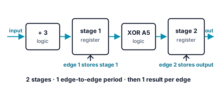
The example below computes (data_in + 3) ^ 8'hA5 in two register stages. valid_in travels through a matching one-bit pipeline so the receiver knows when data_out belongs to a real input.
Latency language needs a convention. A value stable before edge 1 is captured by stage 1 at edge 1 and captured by the output register at edge 2. It therefore crosses two register stages and two sampling edges, while the elapsed time from its capture edge to its output edge is one edge-to-edge clock period. If a specification says only “two-cycle latency,” ask what it counts: occupied stages/sampling edges or elapsed periods after acceptance. This page reports both instead of relying on that ambiguous phrase.
Predict before running
Place decimal inputs 10 and 20 on this four-edge trace before revealing the output. The first input makes stage 1 store 13 (8'h0D). Predict both valid output values, then answer: are you counting two register stages/two sampling edges, or one elapsed edge-to-edge period from acceptance to result?
| Immediately after edge | Stage 1 valid/data | Output valid/data |
|---|---|---|
| 1 | ? | ? |
| 2 | ? | ? |
| 3 | ? | ? |
| 4 | ? | ? |
`timescale 1ns/1ps

module pipelined_transform (
  input  wire       clk,
  input  wire       rst,
  input  wire       valid_in,
  input  wire [7:0] data_in,
  output reg        valid_out,
  output reg  [7:0] data_out
);
  reg       valid_stage1;
  reg [7:0] data_stage1;

  always @(posedge clk) begin
    if (rst) begin
      valid_stage1 <= 1'b0;
      data_stage1  <= 8'h00;
      valid_out    <= 1'b0;
      data_out     <= 8'h00;
    end else begin
      valid_stage1 <= valid_in;
      data_stage1  <= data_in + 8'd3;
      valid_out    <= valid_stage1;
      data_out     <= data_stage1 ^ 8'hA5;
    end
  end
endmodule

module tb;
  reg clk, rst, valid_in;
  reg [7:0] data_in;
  wire valid_out;
  wire [7:0] data_out;

  pipelined_transform dut (
    .clk(clk), .rst(rst), .valid_in(valid_in), .data_in(data_in),
    .valid_out(valid_out), .data_out(data_out)
  );

  always #5 clk = ~clk;

  initial begin
    clk = 1'b0;
    rst = 1'b1;
    valid_in = 1'b0;
    data_in = 8'd0;

    repeat (2) @(posedge clk);
    @(negedge clk);
    rst = 1'b0;
    valid_in = 1'b1;
    data_in = 8'd10;

    @(posedge clk); #1;
    $display("CYCLE 1 valid=%0b", valid_out);
    if (valid_out !== 1'b0) begin $display("FAIL CYCLE 1"); $finish; end

    @(negedge clk);
    data_in = 8'd20;
    @(posedge clk); #1;
    $display("CYCLE 2 valid=%0b data=%02h", valid_out, data_out);
    if (valid_out !== 1'b1 || data_out !== 8'hA8) begin $display("FAIL CYCLE 2"); $finish; end

    @(negedge clk);
    valid_in = 1'b0;
    data_in = 8'd0;
    @(posedge clk); #1;
    $display("CYCLE 3 valid=%0b data=%02h", valid_out, data_out);
    if (valid_out !== 1'b1 || data_out !== 8'hB2) begin $display("FAIL CYCLE 3"); $finish; end

    @(posedge clk); #1;
    $display("CYCLE 4 valid=%0b", valid_out);
    if (valid_out !== 1'b0) begin $display("FAIL CYCLE 4"); $finish; end

    $display("PASS");
    $finish;
  end
endmodule
Expected output — reveal after you predict
CYCLE 1 valid=0
CYCLE 2 valid=1 data=a8
CYCLE 3 valid=1 data=b2
CYCLE 4 valid=0
PASS
Compare your four-edge trace
| Immediately after edge | Stage 1 valid/data | Output valid/data |
|---|---|---|
| 1 | 1 / 0d |
0 / 00 |
| 2 | 1 / 17 |
1 / a8 |
| 3 | 0 / 03 (ignored) |
1 / b2 |
| 4 | 0 / 03 (ignored) |
0 / a6 (ignored) |
The first result is 8'h0D ^ 8'hA5 = 8'hA8. On the same edge that output is captured, stage 1 accepts the second input and stores 20 + 3 = 23 (8'h17). One cycle later, 8'h17 ^ 8'hA5 = 8'hB2 appears. Non-blocking assignments are essential here: data_out reads the old stage-1 value while stage 1 schedules its next value.
Simulation, synthesis, and implementation are different claims
- Simulation: the self-checking testbench proves the two-register-stage valid/data alignment for two back-to-back inputs: capture at edge 1, result at edge 2. It does not measure physical clock speed.
- Generic synthesis: the automated tutorial test runs two separate Yosys flows. Conservative
prepretains coarse registers and operators for claim-scoped inspection; the complete genericsynthscript separately proves that synthesis finishes. Because8'hA5is constant, synthesis simplifies the^expression into wires and inversions for selected bits; it does not need a general two-input XOR cell. Neither pass is a technology-specific area or timing report. - Implementation: a target tool may optimize, retime, duplicate, or map logic differently. Only a placed-and-routed timing report can show whether a chosen device and clock constraint meet timing. This tutorial makes no frequency claim.
Limitations
- There is no backpressure. A downstream block cannot pause this pipeline; add a ready/valid protocol only after learning its cycle rules.
- The example always calculates stage data, even when
valid_inis low. Consumers must ignoredata_outwhenvalid_outis low. - Reset is active-high and synchronous. Changing reset style changes startup and implementation behavior.
- Pipelining trades latency and registers for shorter combinational paths; it does not automatically make every design faster.
Sources and verification
- IEEE 1364-2005 — Verilog language semantics
- MIT OpenCourseWare — Pipelining
- Yosys documentation — generic synthesis scripts
Example provenance: SkillLift Labs authored this design, testbench, diagram, and cycle table. tests/scripts/tutorial-verified-examples.test.ts compiles it in strict Verilog-2005 mode with Icarus Verilog, runs the self-checks, and requires exact agreement with both the published output and a code-owned transaction-delay reference model. tests/scripts/tutorial-tut8-synthesis.test.ts also compiles with warnings enabled, inspects a conservative Yosys prep netlist for the claimed registers, add operation, and constant-mask inversion logic, then requires a separate generic synth pass to finish. Automation verifies only those stated properties; human technical approval and target-specific implementation review remain separate gates.